Hardware Fundamentals
© Copyright Brian Brown, 1992-1999. All
rights reserved.
This material may not be reproduced in printed or electronic format
without the express permission of the author.
![]()
![]()
Hardware Fundamentals
© Copyright Brian Brown, 1992-1999. All
rights reserved.
This material may not be reproduced in printed or electronic format
without the express permission of the author.
![]()
![]()
STORAGE DEVICES
The objective of this section is to
![]() Disk
Storage
Disk
Storage
Disks are used to store data, applications software and operating systems
software. Whereas the primary form of storage in the early days of computing
was magnetic tape, this has been replaced by predominantly disk based medium
today. The reasons for this trend has been
Disk storage systems are essentially based on magnetic properties. This is the same principle as used in cassette tape recorders. A rotating disk is coated with fine magnetic particles. When writing data, a write head magnetises the particles on the disk surface as either north or south poles. When reading data, a read head converts the magnetic polarisation's on the disk surface to a sequence of pulses.
The read and write heads are generally combined into a single head unit. There may be more than one read/write head. Consider the example shown below, where a group of heads is used to write data onto concentric rings on the magnetic drum. In this example, the heads are fixed (non-moveable).

Fig 5.1: Magnetic Drum
The problem with this drum approach is limited capacity. To increase the capacity requires an increase in the circumference size of the drum, or more read/write heads.
A more common approach used today is to use a read/write head attached to a moveable arm, which steps across (by small increments) the surface of the disk. The disk is a platter coated with magnetic particles. This arrangement is shown below.

Fig 5.2: Hard Disk Drive
Early drives were large. IBM developed a smaller rigid disk drive with one fixed and one removable pack. Each pack held about 30 megabytes (MB) of data, so it was dubbed model '3030', and became known as the Winchester drive.
Most Winchester drives have common features

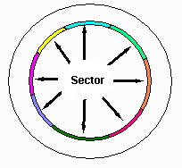
Fig 5.3: A track subdivided into sectors
The smallest unit that can be written to or read from the disk is a sector. Once a read or write request has been received by the disk unit, there is a delay involved until the required sector reaches the read/write head. This is known as rotational latency, and on average is one half of the period of revolution.
The storage capacity of the disk is determined as (number
of tracks * number of sectors * bytes per sector * number of read/write
heads)
![]() Disk
Drive Characteristics
Disk
Drive Characteristics
This section discusses the terminology and characteristics of disk
drives.
Tracks and Sectors
The disk is divided into concentric rings called tracks. A track is
thus one complete rotation of the disk underneath the read/write head.
The width of a track is determined by the size of the read/write head,
and the distance between tracks determined by the mechanics of the stepper
motor which controls the positioning of the arm to which the read/write
head is attached.
Each track is subdivided into a number of sectors. Each sector contains a specific number of bytes or characters. Typical sector capacities are 128, 256, 512, 1024 and 4096 bytes.
Increasing the number of tracks is one way to increase the storage capacity of a disk drive. Often the physical size of the disk imposes space restrictions which make this impractical. The most common choice is increasing the number of sectors per track (from 17 to 34), or increasing the number of bytes stored in each sector.
Bad Blocks
The drive maintains an internal table which holds the sectors or tracks
which cannot be read or written to because of surface imperfections. This
table is called the bad block table, and is created when the disk
surface is initially scanned during a low level format.
Partitions
A disk partition is a sub-division of the disk into one or more areas.
Each partition can be used to hold a different operating system. The computer
system boots from the active partition , and software provided allows
the user to select which partition is the active one.
Sector Interleave
This refers to the numbering of the sectors located in a track. A one
to one interleave has sectors numbered sequentially, 0, 1, 2, 3, 4, etc.
The disk drive rotates at a fixed speed, 3600rpm, which means that there
is a fixed time interval between each sector. A slow computer can issue
a command to read sector 0, storing it in an internal buffer. Whilst it
is doing this, the drive makes available sector 1, but the computer is
still busy storing sector 0. Thus the computer will now have to wait one
full revolution till sector 1 becomes available again.
Renumbering the sectors like 0, 8, 1, 9, 2, 10, 3, 11 etc gives a 2:1 interleave. This means that sectors are alternated, giving the computer slightly more time to store sectors internally than previously.
Drive Controller
The drive is managed by a special peripheral card called a drive controller.
It may handle multiple drives or only a single drive. The controller is
often responsible for issuing commands to position the read/write head
(especially in MFM and RLL drives).
In SCSI and IDE drives, the controller is simplified, and the intelligence is placed onto the drive itself. These drive offer sophisticated features like caching and hot fix (write errors are redirected to another free sector).
Rotation Speed
This refers to the speed of rotation of the disk. Most hard disks rotate
at 3600rpm. To increase data transfer rates, higher rotational speeds are
required, or multiple read/write heads arranged in parallel, or disk arrays
(multiple disks arranged in parallel).
Low/High level Formatting
Low level formatting is placing track and sector information, plus
bad block tables and other timing information on the disk. Sector interleave
can also be specified at this time.
High level formatting involves writing directory structures and file allocation tables to the disk. Often this also means transferring the boot file for the operating system onto the hard disk.
Access Time
Access time refers to how soon the drive makes data available once
issued with the command to read the data. Once a read command is issued,
the drive must position the read/write head at the appropriate track number
and wait for the correct sector to arrive.
Latency
This refers to the delay between the read/write request, and the appearance
of the required sector under the read/write head.
Timing tracks
In larger drives used on main frame computers, the disk drives often
had timing tracks written. These tracks were used for alignment purposes,
to ensure that the read/write head was accurately positioned over the track.
The read/write head was moved until the pulses picked up from the timing head were at a maximum. This meant that the read/write head was correctly positioned over the data track.
Newer more accurate mechanisms have tended to make this obsolete.
![]() Hard Drive Construction
Hard Drive Construction
This picture shows the physical construction of a hard disk drive.

Fig 5.4: Hard Disk Drive Construction
![]() Disk Drive Types
Disk Drive Types
This section discusses the various drive types available for IBM-PC
compatible computers.
![]() Floppy Drives
Floppy Drives
The floppy drive uses a thin circular ceramic disk for data storage.
The disk is coated with magnetic particles and is flexible (hence the term
floppy).
The disk rotates at 360rpm. A read/write head makes physical contact with the disk surface. Data is recorded as a series of tracks subdivided into sectors. Typical values for an IBM-PC compatible are
| Size | Capacity | Tracks | Sectors |
| 5º | 360KB | 40 | 9 |
| 5º | 1.2MB | 80 | 15 |
| 3? | 720KB | 40 | 18 |
| 3? | 1.44MB | 80 | 18 |

Fig 5.5: 5.25" Floppy Drive
The two main methods of identifying the beginning sector of a track are

Fig 5.6: Floppy Drive Cleaning Kit |
The image on the left shows a floppy diskette cleaning system. It consists of a floppy disk containing a cleaning disk and some cleaning fluid. The fluid is placed on the floppy disk and then the disk is inserted. Any foriegn material on the read/write heads are transferred to the disk. The cleaning disk can only be used a limited number of times. |
![]() Hard Disks
Hard Disks
Hard disk drives use a thicker non-flexible disk. The disk is made
from aluminium or ceramic material, and coated in magnetic particles. The
disk rotates at a much higher speed (3600rpm). In addition, multiple disks
are stacked on top of each other (with a gap in between), with a read/write
head allocated for each surface (top and bottom).
Storage capacities range from 10MB (first PC disk used in XT) to several gigabytes.
This allows a flexible method of data storage. As each disk pack becomes full, it can be removed and a new pack inserted to handle the next lot of transactions etc.
Home | Other Courses | Notes | Tests | Videos
© Copyright Brian Brown, 1992-1999. All rights reserved.